|
Since the Mustang was wrecked, I ended up stripping everything usable from the vehicle that I could sell, leaving only
those components that were pertinent to the project (steering column, suspension, rear end, brakes) and cutting out all of
the crushed sheet metal from the bottom of the windows up, leaving a former shell of a car behind. Since this vehicle
is going to serve the purpose of what would amount to an oversized golf cart, its not like this thing really needs as much
as a street legal vehicle would need in order to function. No fancy gauge panels, fenders, no nice interior or doors,
this is as basic as basic can get.
|
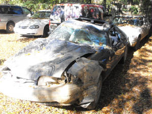
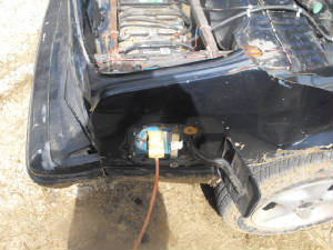
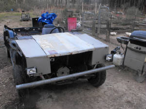
| Shot of the wrecked car from the front |
|
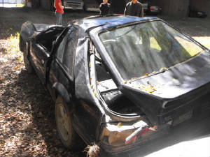
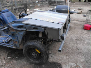
| Shot of wrecked car from rear |
As stated before, I ended up stripping all of the usable parts from the vehicle, the engine/tranny, most of the interior including
the dash and HVAC box, fuel tank, anything that was bolted down came out. By the time I was done, all that was left
was the rolling chassis with the steering column attached. Afterwards I removed the crumpled panels, with the passenger
door and rear hatch being the only things salvageable from the car, they're currently on craigslist. Everything else
went into a scrap pile. Next I took the reciprocating saw and commenced to hacking up the front end, which had a severely
twisted frame. I ended up cutting right in front of the shock towers, leaving the important suspension parts but omitting
the sway bar, since this vehicle wouldn't be going super fast, it wasn't a necessary component to worry about. Afterwards
I started from just below the windows and cut all metal off going back. Basically it looked like the car drove under
a semi trailer when I was done. All insulation, wiring, everything came out.
At that point
I removed the EV hardware from the Falcon and loaded that stuff on the truck to haul up to the garage, with the next thing
being the pulling of the Mustang chassis to the garage to be parked for the time being. After that was all said and
done I was able to start installing everything. Since the mounting hardware for the 88 Mustang was very similar to the
69 Mustang and Falcon, the tranny mount went in just fine, and the improvised electric motor mounting points sat right above
the 88's motor mounts, leaving me to not have to do a lot of fabricating with scrap metal to make motor mounts to connect
the front of the electric power train to the 88's chassis.
Early February 2013:
With putting the motor/tranny into the chassis, I got to work on all the other odds
and ends. Since I had to disconnect many wires and cables, I had to figure out where a few things went, which actually
didn't take too long. The main thing was getting the established cable routes for the intermediate voltage system so
when I got the batteries installed, all I had to do was route the cables down the length of the chassis and hook them up.
Everything else I had figured out, ammeter and charge meter, pot box, and automotive relays. I installed the auto
relays and hooked up all wiring that was in the immediate vicinity of the motor controller/contactor platform right above
the motor.
The next thing that I had noticed was because the frame was bent severely on the
right side, the right front tire would rub hard on the rear of the fenderwell when the steering was turned all the way to
the right. To solve this problem I ended up putting the donut tire on that side, which was obviously smaller than the
15" rim/tire that was on there. Later on I ended up getting another of the same exact tire from the junk yard to put
on the left side to even it out. Later on I'll probably just find a pair of 14" rims for that car and put the smallest
tires I can get on the rims to achieve the same effect.
I did have to fabricate a makeshift
mount for the pot box to get it secured, and to be able to use the stock throttle cable, which in the end actually worked
out flawlessly. With that, I installed the main cut off switch on the transmission hump in front of where the shifter
would go. I had some short lengths of 2/0 cable on hand that allowed me to hook up one end of the switch to one of the
inputs of the power system. This allows the driver to instantly turn off main power to the higher voltage system in
case of an emergency.
The next thing that went in was the shifter. Now, before the car
was wrecked, I had converted the car to an auto tranny, but because I was unable to find a stock shifter, I ended up grabbing
a shifter from a late 90's Mustang in the junk yard. That hook up was sort of Mickey Mouse, but it worked. Rather
than spend unnecessary money or time figuring out something that was cosmetically better, I stuck with what I had, so the
shifter went back in. I strapped it down with a strap of metal and bolted the other end down, then fabricated a shifter
linkage for the transmission using some narrow width flat stock metal, which again, worked pretty good, for what I wanted
to do. I didn't really want the shifter to be able to put the tranny in park since I didn't have a way to cut off the
motor when the thing is in park (revving up an electric motor while in park will probably frag the parking pawl in the transmission).
So at best, I was able to hook the linkage up where I have reverse, 1st gear and 2nd gear, with the manual valve body,
that was more than satisfactory as I will later find out.
|
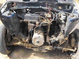
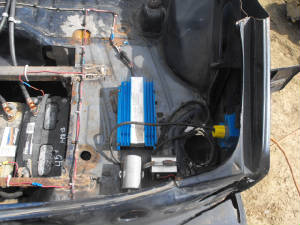
| Motor/trans in place with controller rack bolted down |
With the shifter in place, I then went ahead and installed a spare seat I had that was pulled from the car in the past. While
it's a passenger seat, I didn't care, its only one seat, and in the future if I find another driver's seat at the junkyard
I can just swap them and be done with it, its not like there's going to be seat belts or a center console to get in the way
of the recline mechanism so anyway, the seat went in so now the driver can at least SIT.
Next I
proceeded to the rear and commenced to work on mounting the battery rack. This started off by measuring and welding
up a frame to accommodate four larger marine batteries that you would commonly get from Walmart or Sam's, 27DC batteries I
believe. After making the rack frame, I then measured and cut out a section of the trunk floor, which included most
of the spare tire well, then welded in the rack so the batteries will hang low under the car, giving a flush surface in the
rear, which will allow for my wooden carry-all bed to be installed with ease later on.
With
the battery rack in place I then installed the Capacitor battery charger unit, which takes direct 120 VAC, rectifies it to
DC, then self regulates the voltage to that of the battery pack that its charging, using the battery pack itself and its capacitor
so instead of metering 120 VDC on the closed circuit, you only measure the 50 something volts that the battery pack produces.
Its a nifty setup that literally allows you to recharge literally any voltage battery w/o the use of complex regulation
circuitry. Along with the battery charger I installed a DC/DC converter that takes 24 VDC and converts it to 13.8 VDC
for recharging an accessory battery. I also installed said accessory battery, which was a batter that came from our
old diesel escort that we long since sold after having serious problems with it.
From there
the wiring was installed for everything, being done neatly with the wire runs running together, wire tied, and secured on
the surface of the sheet metal with clamps to make for very neat wire runs instead of the spaghetti bowl of wires that I used
to be guilty of doing in the past. I also installed metal braces on the outlet box for the battery charger and bolted
the outlet box right in the hole where the fuel filler door is, for a bit of a humorous touch. A junkyard ground cable
went from the accessory battery to the chassis to hook the battery up, and a wire run for the 12v system was run along the
driver's side rocker panel up to the steering column and to the ignition key switch to allow for turning power on to the low
voltage side of the system using the key. The 24 v line required for switching the main contactor was also run from
the battery pack along the same route and up to the auto relay in the front so it can be switched on and off via said relay.
Everything was secured using wire ties and clamps.
|
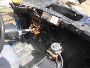
| Pic of "interior", note cut off switch and gauges near top |
|
| Outlet box for battery charger, installed behind fuel filler door, just for a laugh |
|
| Capacitor battery charger and DC converter, note battery rack to left |
|
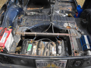
| Shot of accessory battery, battery pack/rack, DC converter and charger, left to right |
Coming close to completion, the next thing was the pair of cables going from the battery pack to the front and into the
motor controller assembly. I ended up finding some lengths of cable that were surprisingly long enough to reach where
I needed them to go. The only thing I needed were the large copper terminals that were intended for clamping to the
ends of thick cable and securing to the threaded stud posts of things like these marine batteries. With the terminals,
I was able to get the cable runs set up, again, using clamps, this time conduit clamps, to neatly secure the thick cable to
the center hump.
With everything now hooked up, and the batteries being charges as I had the
battery charger plugged up the whole time (disconnected while hooking up cables of course), I went ahead and turned the system
on to see if everything worked, which it did, motor came on, varied in speed based on the throttle position, everything was
good to go. The only thing left at that point was a driveshaft, since the old shaft was too long and the yoke needed
to be changed since the C3 tranny that was in there was smaller than the C4 that's on the current power train.
Meanwhile,
I had to plug up the hole where the speedometer cable gear normally goes into the tranny. Since there is no speedo,
I had to figure something out. Luckily, the gear that came from the Mustang was also a sensor which was separate from
the cable which was actually perfect. I was able to bolt the thing in place to plug that hole, no problem.
When
the driveshaft came in, I hooked it up and filled the tranny with oil. I powered everything up and back to life the
car came. The tranny grabbed just fine, I was able to back the thing up out of the garage and take it for a test drive
down the driveway and down our gravel access road down to the mailboxes, approx 1/2 mile give or take, and back, with no problems,
other than some tranny oil leaking. That was partially solved by putting better hose clamps on the hose going between
the in/out oil lines on the transmission. The trans oil pan will need a new gasket as well, and it looks like the front
seal might be shot. With the hose clamps being replaced I cut down the oil leakage by about 75%. The gasket should
improve that number, then there's the front seal, which for all intents probably won't be replaced any time soon as that'll
be a bit of a pain in the ass, even on this setup. I'll figure something out though.
The
next thing I did after the completion of the base EV was install a pair of fog lights to serve as headlights for when I have
to use the vehicle at night. This was accomplished with a Harbor Freight special at $13, a little bit of wiring and
crimp connectors, and about 30 min of time. The switch is hooked up just to the right of the gauge panel for easy access.
Those lights actually light the way pretty good too.
With that, the next thing on the
agenda will be a bumper of some sort for the front, plus some type of shield or cover to cover up the motor controller in
the front, along with something to cover the DC converter and charger in the rear so if it rains, that stuff won't get wet.
The only thing I'll have to do at that point will be to put a smaller tarp over the seat to keep it dry, since right
now a large tarp is used to cover most of the car up when the weather is questionable. But for now, the EV is complete
and is already serving its purpose as a utility vehicle around the homestead. There will be more to come as I continue
to build on this thing.
|
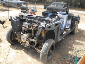
| Shot of EV from front left angle |
For those of you techies who are interested in details about the hardware used on this vehicle, I will tell you. First
of all, the motor used is an older model Advanced DC 8" series motor with a splined shaft, operating voltage between 48 and
80VDC. The transmission is a typical C4 automatic transmission with the torque converter removed and the hub that goes
into the input shaft incorporated into the coupling for the motor, all customized by a machine shop. The motor is direct
coupled to the transmission's input shaft so when the motor is powered up, there is a lag time when the trans pump has to
get oil circulating through the hydraulic system before the output shaft starts turning. Usually its not too slow, it
can be pretty instantaneous if you accelerate pretty hard, but then you risk tearing up the hardware that's not used to having
that kind of torque thrown on it from a dead stop so we just baby the thing from a dead stop til it starts moving before depressing
the accelerator.
The linkage on the transmission only allows reverse and 1st/2nd gear, which is
fine for this application. When in 1st, from a dead stop the motor will draw approx 400 amps then quickly taper down
to just below 200 amps and at a full wind up hover around 150. In 2nd gear it'll peak back to near 400 amps as the system
tries to get up to speed, causing the amperage to go back down. Now this vehicle hasn't been put through any time trials
yet to see just what its capable of doing, so for the time being, we usually keep it in 1st, so as to not push the system
too hard.
The motor controler is a Curtis controller, rated voltage from 48-72 VDC, 400 amps.
Pot box is a generic aftermarket unit bought off Ebay. Contactor is a general industrial unit rated for DC power
and shunt is a unit intended for EV use, rated up to 1000 amps. The charge gauge is a generic unit that's rated for
a 48 vDC system and ammeter goes up to 1000 amps. The batteries are typical 27DC ever ready and similar brand marine
deep cycle batteries, rated around 200 something amp hours. The DC converter is a 24-13.8VDC, 10 amp unit, picked up
from a flea market and capacitor battery charger charges around a couple amps with the given value capacitor in the system.
Further experimentation with cap sizes will hopefully yield a higher amperage charge w/o compromising the system.
The
most expensive part of the vehicle was the adapter plate and coupling from the machine shop, coming in at $1k. The motor
was had off of Ebay for $600, everything else was had at less than retail as well.
Other future
plans for this vehicle also include a generator for hybrid use, we'll see.
3-8-13: Well so far we've been using the EV for routine tasks around the homestead, going down the gravel road
to the mailbox or to take down the trash cans, transporting large amounts of project related stuff between the garage and
the house (about 100 yds) and just flat out recreational driving up and down the road. As usual, there are bugs that
have to be worked out, the biggest ones being the C4 transmission's willingness to leak for no reason at all. Well,
I did replace the length of rubber hose and worm clamps that coupled the in and out oil lines, which eliminated one leak,
but there's still the oil pan gasket which appears to be leaking, and *ugh*, the front main seal. Needless to say, the
front main seal won't be getting replaced any time soon, but the pan gasket will get replaced soon.
The first thing that I did was fabricate a bumper assembly and frame extention to accomodate the bumper. This was
done by taking some scrap cubicle railing and welding it in place on the frame stubs where I previously cut the old frame
out. After making the extensions, I took a fence post and welded it in place on the ends of the frame rails, only having
to cut about a foot off of the overall rail. This setup will be the start to the whole body setup.
The next thing to be addressed is the simple idea that a body needs to be fabricated in order to protect the hardware
in the front and back, along with the seat and gauges in the cab. Of course this is one of those things that has to
be done one at a time. In this case, we worked on fabricating a front end for the EV. Trying not to spend money
and utilize junk that we already had lying around in the scrap pile, I dug out sections of cubicle panels we acquired a couple
years ago. These panels will be used to fabricate inner fender panels, along with top panels, which would then allow
for a small gap to lay a makeshift hood over the hardware in the front of the vehicle.
One of the first things that had to be done was to extend the wires for the headlights in order to mount them in a new
location. Afterward, two of these panels were trimmed and welded over the left and right sides over the shock towers,
with about an extra foot or so of panel hanging out to the front. This extra panel on each side was cut and bent down
to fabricate a front end, with a tab cut and bent out on the lower outer corners of each panel in order to mount the headlights.
With the side panels/fenders installed, I took a piece of sheet metal that used to be the skin from a water header, cut
it and bent a tab to hold it over the front, while securing the rear section of this "hood" with sheet metal screws over the
panel right in front of where the windshield used to be.
Right now this is still a sorta temporary installation of the hood, in order to lift the hood up, I have to remove two
screws in the front from that tab I mentioned, and just bend the sheet metal upwards to access the hardware underneath. My
next plan will be to A: install a small piece of angle iron across the front of the body, between those two side panels mentioned,
in order to install some type of makeshift latch that can be released and secured easily. B: Install a stiffening
panel under the sheet metal hood to give the thing more rigidity so it doesn't rattle. C: Install hinges in the
rear to allow the hood to be raised like a normal hood would be.
This setup will make for a more normal setup that will accomplish the goal of protecting the hardware in the front from
rain or sunlight. I will kill two birds with one stone when I make the pickup bed and make cover panels that will go
out from the left and right sides of the bed over the car's old fenders, effectively covering the hardware in the rear. The
last thing will then be the roof. More to come.
|
| Newly fabricated front end, note location of headlights |
|
| Side view of panel setup |
3-9-13: Today I was able to do the first of a couple of tests (maybe more) on the EV. This test was really not
so much a time trial as it was a top speed trial. I will probably do a time trial to see just how long it takes to reach
top speed, but this first test was to see just how fast the vehicle can go in its current state. I had to have the wife
pace me with the truck to relay my speed in real time via 2-way radio while I was driving.
We
traveled to the paved roads to do the tests in order to get a more accurate assessment of the performance, so we're looking
at something like a 1/3 mile to maybe a half mile before reaching the stretch of road we were to use. From there I just
depressed the accelerator and let the motor wind up in first gear. Because the motor controller has a top end of 400
amps, no matter what the motor is capable of pulling, its only going to get a maximum of 400 amps. Well needless to
say it didn't take long for the vehicle to top off in first gear, which was recorded at around 20 mph. After holding
it there for 30 seconds just to make sure there wasn't any more juice left in that gear and getting a final speed recorded,
I put the vehicle into 2nd gear and watched the ammeter jump back up to 400 amps, from the 150 amps it drew at top end in
1st gear.
Well needless to say it was pretty exciting at that point, the car started getting
faster and faster. It did take a while for it to get up to speed but it was getting there. I got up to 30 mph,
then after a while it pushed itself up to 35 mph. Granted we were on some uneven road with some inclines and slopes.
While it was bouncing a little above 35 we went into a slight downward grade and the car reached 40 mph and held itself
there even after leveling off. I was able to keep the car at 40 mph for the last 3/4 mile before we ran out of road.
We turned around and repeated the same thing again, getting similar results, with the top speed pretty much settled
on as 40 mph for the vehicle in 2nd gear.
Now granted the tranny is a 3 spd, but the linkage
which was fabricated, doesn't really allow me to go into 3rd, and for all intents its probably better that way, as the motor
in that high gear would probably draw 400 amps the whole way. Then again, who knows, I will never really know until
I get the linkage hooked up where I have full range of use through the gears. For now a top speed of 40 mph is more
than enough for a vehicle that is rear end heavy with the batteries and the front end up in the air on donut tires. We're
not really trying to have a highway cruiser anyway. Maybe in the future after doing everything else I plan on doing
to the vehicle I can explore trying to make the thing go faster just for the sake of being able to say I can. With the
addition of a roll cage and extra seat and homemade carry all bed, the weight increases will drop the top speed down more.
Again, since this vehicle is a utility vehicle and not a street legal highway capable vehicle, we really don't need
it to go super fast right now. Especially without some type of windscreen to protect the face....
More
to come....
|


